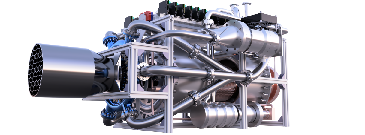
This is P.H.A.N.T.O.M., a thruster designed to be both a test bed for new technologies and a tool for use in very low-Earth orbit. P.H.A.N.T.O.M. is highly customisable due to its aluminium strut frame, which allows for the frame to be changed around just by loosening a few bolts. P.H.A.N.T.O.M. can operate in environments for long periods of time where no other thruster can, such as low-Earth orbit, where erosion of components in a typical plasma thruster is a concern. P.H.A.N.T.O.M. avoids this issue by using helicon waves to interact with the plasma without needing to even touch it. P.H.A.N.T.O.M. is designed with reliability in mind, where the ultra-high vacuum components have backups of backups using a double-layered design—so if one fails, there is still another to keep the efficient low-temperature superconducting magnets insulated. P.H.A.N.T.O.M. is also capable of operating outside of Earth's atmosphere with the use of an argon gas injection system. This gives P.H.A.N.T.O.M. unprecedented performance over other thrusters while using only 10 kW of power.
The thruster, as shown in the images, is a helicon thruster—a relatively new concept for advanced electric propulsion systems. Its main attribute is the use of helicon waves, which are low-frequency electromagnetic waves around 15 MHz, instead of conventional electromagnetic waves in the GHz range. There are many benefits to using lower-frequency electromagnetic waves. Generally, the lower the RF frequency, the more efficient the system will be, as transmission losses are reduced.
The working name for the thruster I have designed is P.H.A.N.T.O.M., which stands for Pulsed Helicon-Atmospheric-Noble Thruster with Optimised Magnetics. This name reflects the thruster’s ability to use both atmospheric gases and argon injected into the chamber as propellant.
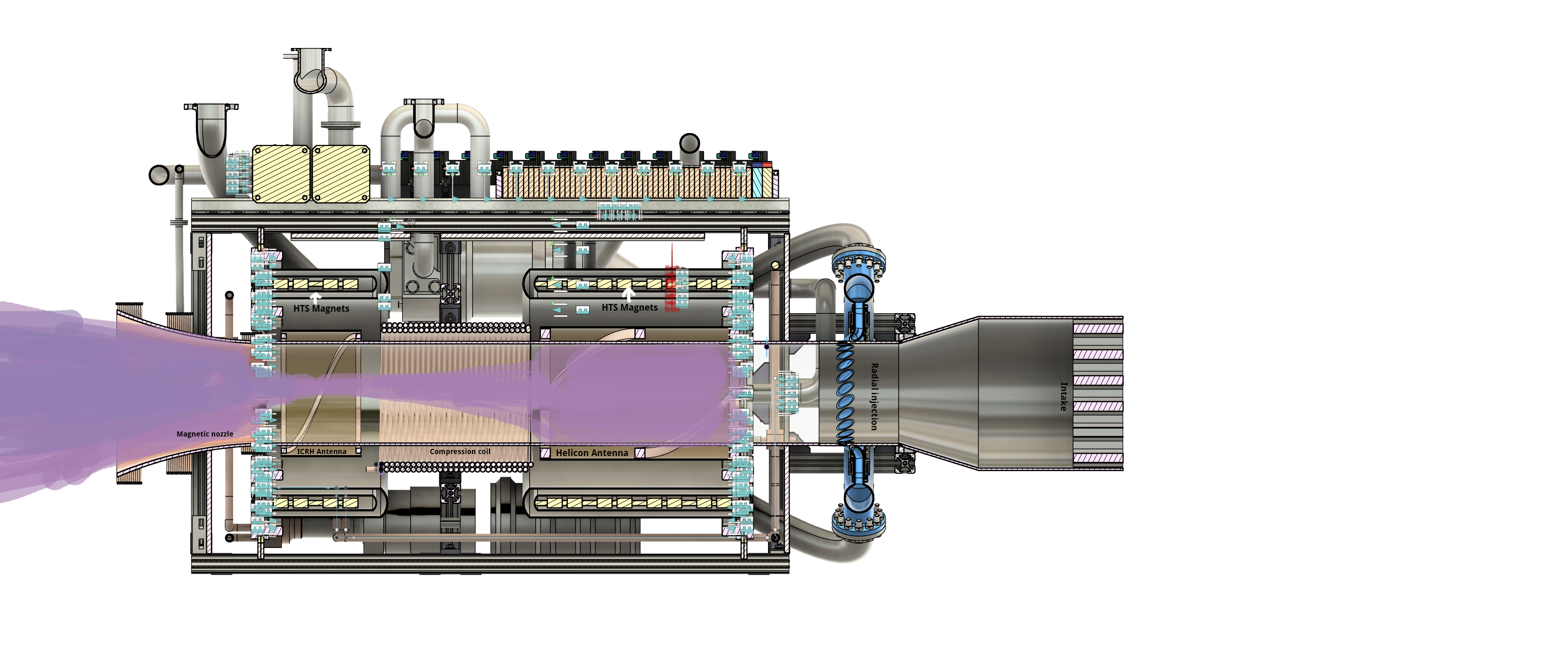
A hexagonal intake was designed, as the hexagon shape helps increase back pressure in environments with high rarefaction, such as very low-Earth orbit. The injection system is angled to create a rotating flow in the chamber, and small pulsed helicon antennas are placed in each injection pipe to allow for pulsed control, improving the flow of gas inside the chamber.
Once the gas enters the chamber, it approaches a section where a half-helix (helicon) antenna is located just outside the chamber, as shown in the diagram. This is within a 0.08 Tesla magnetic field, which facilitates ionization at lower energy levels. When a 14.2 MHz RF current is applied to the helicon antenna, helicon waves are generated—named for the helical shape in which they propagate.
When these helicon waves interact with the gas inside the chamber, several things occur. First, the waves ionize the gas particles, creating plasma. Then, due to the rapidly changing wavefronts in the environment, ponderomotive forces, Lorentz forces, and ambipolar currents are generated. These effects work together to impart net momentum to the gas particles.
The particles then travel to the compression coil, which induces electron currents in the outer layer of the plasma. These currents generate Lorentz forces that push the plasma inward, compressing it. Once compressed, the gas reaches a section analogous to the throat of a combustion chamber, where the Ion Cyclotron Resonance Heating (ICRH) antenna is located.
Another set of HTS magnets is positioned here, generating a 4-Tesla field similar to that found in an MRI. When a high-frequency RF current tuned to the ion cyclotron frequency is applied, waves propagate from the ICRH antenna, rapidly heating the plasma from approximately 5,000 K to 1,000,000 K. This significantly increases the plasma’s energy density and pressure.
Finally, the plasma is expelled through a magnetic nozzle, which is designed to prevent the gas from contacting the chamber walls while maintaining a bell-shaped profile to enhance efficiency—resulting in thrust